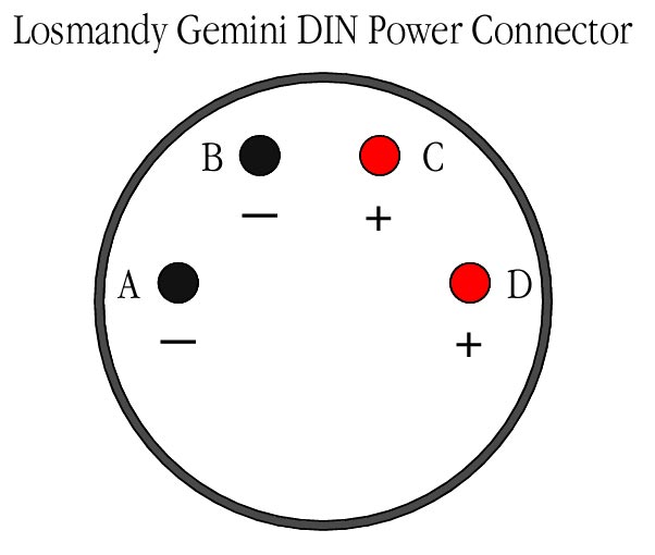
The power cable that is supplied with the Gemini Controller has four conductors—two red and two black. There is a four-pin DIN connector at one end of the cable and an automobile plug on the other end. The DIN connector plugs into the Gemini Controller. In the drawing at top
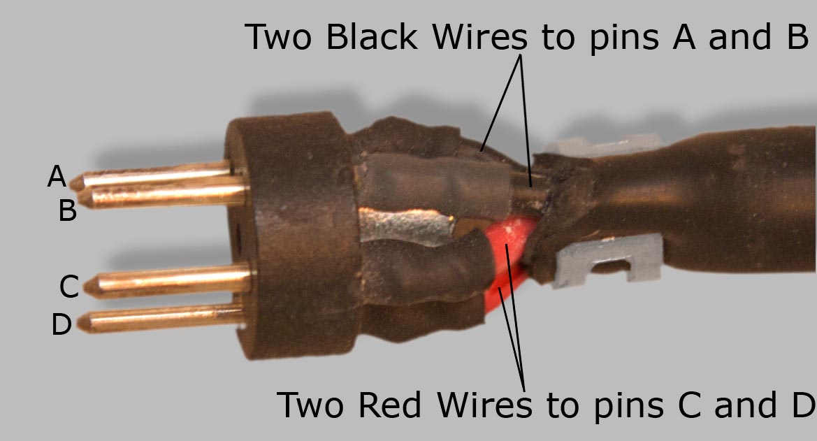
we are looking at the pins that plug into the Gemini controller,
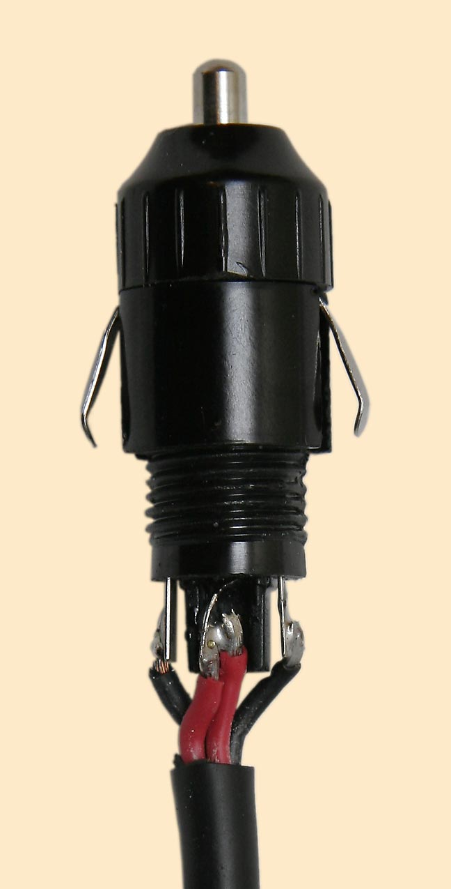
not at the solder connections on the back of the DIN plug. See the photograph above for elucidation. After all plugs are installed and all four wires have been soldered, continuity testing will show continuity between pins C and D, but not between pins A and B. The reason is shown in the photo below—the red wires (C and D) are soldered together at the automobile plug end, where they both connect to the center (positive) pin, while each black wire (A and B) is connected to a different one of the two spring conductors that are positioned on either side of the automobile plug.
Caveat lector.
Bluebell
Internet Services, LLC, owner of this web site, cannot guarantee that your power plug should
be wired in this way. If in doubt, use a Volt-Ohm Meter (VOM)
to test continuity and check for shorts. If you do not know what “use a Volt-Ohm Meter (VOM)
to test continuity and check for shorts” means,
seek professional assistance. Bluebell Internet
Services, LLC, will not be held liable for any damages, whether
they arise from injury to your person or any other persons, or
from damage to any equipment or property, that may arise from
your attempt to use the information contained on this page or
on any other page or in any document that is part of this web
site. Errors noted in this page may be reported here. |